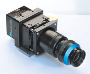
Line scan cameras are semiconductor cameras used in many industrial environments. The single photosensitive line sensor contains – depending on type – up to 22800 picture elements (pixels). Light energy incident on the sensor is transformed into an electric signal for digitization within the camera.
At 8-bit resolution, the A/D converter transmits the output voltage of each pixel into one of 256 brightness levels, at 12-bit resolution into 4096 brightness levels.
Color line scan cameras provide three separate line signals for Red, Green and Blue with either 3 x 8-bit or 3 x 12-bit per pixel. The digitized output signal is transfered to a computer via various interfaces according to requirements, e.g. Gigabit Ethernet or USB 3.0.
The advantages of a line scan camera include
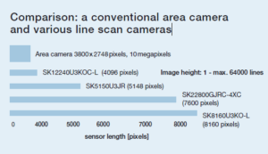
high optical resolution of up to 8160 pixels (monochrome) or 3 x 7600 pixels (color RGB)
high speed of up to 54 kHz line frequency
flexible parameter setting for the line scans
synchronizing of each individual line, as well as the triggering of frames
when focused on the zenith of cylindrical objects, the line scan camera delivers sharp, distortion-free images of the external surface during rotation
flexible image height from 1 up to 64000 lines per image
continuous scanning of endless materials such as foils or paper without a time limit.
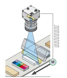
Creating an image
The image produced by a line scan camera is one-dimensional and represents the brightness profile of an object, captured at the current position of the line sensor. A two-dimensional image is generated byperforming a scanning movement of either the object or the camera, during which the individual line signals are transferred to the computer and assembled one by one into a 2D image.
Improving the image
High image quality can only be achieved with the appropriate combination of line scan camera, high resolution lens, appropriate lighting and a precise motor unit, whether rotary or linear drive or a conveyer belt. For an image to be correct in all proportions, the scanning speed and the image acquisition process must be highly synchronized and this is most easily achieved by adjusting thetransport speed to the line frequency of the camera. However, in practice, it is usually the transport speed and the image resolution that are constraining and these predefine the line frequency and ultimate choice of line camera.
At constant transport speeds, such as when examining objects on a conveyor belt, a line scan camera can be allowed to operate in a free‑running mode. Where there are velocity fluctuations or discordant movements then external triggering of the line scan camera is required. The trigger pulses, e.g. from an encoder, are equidistant and independent of the movement velocity so that the camera will be triggered after a constant travelled distance.
This precise synchronization guarantees images with a reproducible resolution and correct aspect ratio.
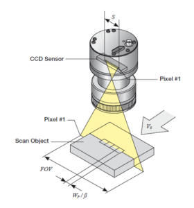
The line frequency fL can be calculated for a given object speed vo and field width FOV, sensor length S and pixel width w from
(1)
The production of a 2D image
The production of a 2D image requires precise synchronization of the line camera sensor and the speed of transport of the object.
Line Scan Camera Applications
Generally, the applications can be grouped into one-dimensional or two-dimensional measuring tasks.
For one-dimensional applications, the measured result is extracted from the pixel information of an individual line scan. Measurements of two-dimensional images require moving either the object or the line sensor.
Camera Application:
1-dimensional
Signal generation: individual line scan
Examples: measurement of width, rod diameter, edge positions, glass thickness.
2-dimensional
Several line scans are combined to produce a 2D image (frame)
NISHANT MOHAN AND CICELY RATHMELL, WASATCH PHOTONICS
Adaptive optics (AO) technology is often used to correct for wavefront distortions imparted when light travels through complex optical systems, enhancing image resolution and facilitating diffraction-limited optics. It has played a particularly prominent role in ophthalmic imaging, where retinal tissue imaging is limited by inherent aberrations in the eye.
Given the widespread adoption of OCT in clinical diagnostics over the last 20 years, these two techniques should be natural partners. But because of technological limitations on both sides, practical applications of AO-OCT have been difficult to implement.
Improved imaging
AO refers to a family of techniques used for correcting distortions or aberrations in a light wave — aberrations that can occur whenever light passes through a translucent yet optically distorting medium such as the atmosphere or the human eye. Though originally developed to overcome the limitations of astronomical imaging through the earth’s atmosphere, AO has facilitated the resolution of many key retinal structures in the living eye since it was first used to observe cone photoreceptors more than 20 years ago1.
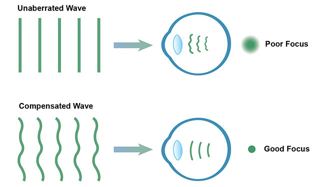
Most ophthalmic imaging techniques use the focusing power of the human eye itself to generate an image of the retina at the back of the eye, so their resolution is limited by diffraction because of the finite size of the eye’s pupil and ocular aberrations. AO mitigates this issue by compensating the initial wavefront for the aberrations experienced when working with a dilated pupil, which provides much better focusing and facilitates image resolution at the cellular level (Figure 1). The ability to visualize cells, organelles, and other microscopic structures, both in vivo and noninvasively, makes AO-based imaging invaluable for medical and scientific applications.
Figure 1. AO uses wavefront compensation to correct for naturally occurring aberrations in the eye, which improves the quality of focus for retinal imaging. Courtesy of Wasatch Photonics.
It has been successfully combined with several ophthalmic imaging techniques along with OCT, including fundus imaging and scanning laser ophthalmoscopy. Of these, OCT is the fastest-growing ophthalmic imaging technology, providing considerably more information about retinal layer structure. This technique has gained clinical importance because of its important role in managing critical retinal disorders such as age-related macular degeneration (AMD) and glaucoma.
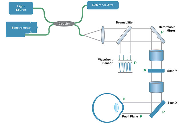
While OCT can provide images at the tissue level in the axial dimension, its transverse resolution is limited by aberrations in the eye; therefore, it cannot be used for imaging at the cellular level without the aid of AO. Combining the two creates a unique and powerful tool capable of 3D cellular imaging, as shown in Figure 2. A wavefront sensor in the detection path is used to measure the wavefront aberration, and a wavefront compensator, such as a deformable mirror, then corrects the aberration in real time.
Figure 2. AO can be integrated into a typical ophthalmic OCT system via the addition of a deformable mirror for wavefront control and a wavefront sensor for active feedback, thus compensating for optical aberrations within the eye. Courtesy of Wasatch Photonics.
Early challenges
Early works in the field of AO-OCT combined adaptive optics with the time-domain variant of OCT. While good at a proof-of-concept level, the slow speed of time-domain OCT limited the application of AO to research use2,3. The development of Fourier domain OCT increased the speed of OCT imaging by orders of magnitude, enabling Zawadzki and colleagues in 20054 to show the combination of AO with Fourier domain OCT for 3D imaging. The technique clearly demonstrated increased sensitivity. However, the OCT acquisition rate was still not fast enough to overcome the motion artefacts that hamper in vivo volumetric cellular-level imaging.
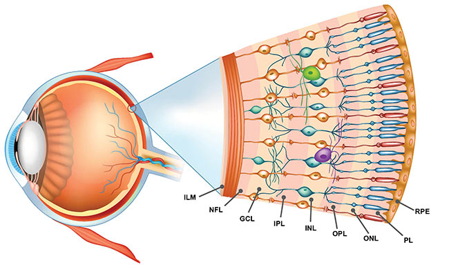
It became clear that the success of AO-OCT in ophthalmology would require a delicate balancing act between all of the parameters of importance, including imaging speed, sensitivity, field of view, and cost. Visualization of microscopic structures within the retina (Figure 3) requires the acquisition of a 3D volume within a very short time frame. To obtain useful medical and biological information, the acquisition must also overcome the so-called keyhole problem, in which field of view limits the retinal patch sampled, providing too little information on global retinal disease to be useful.
Figure 3. Layers of the human retina, as defined by various functional cells. ILM: inner limiting membrane. NFL: nerve fiber layer; GCL: ganglion cell layer; IPL: inner plexiform layer; INL: inner nuclear layer; OPL: outer plexiform layer; ONL: outer nuclear layer; PL: photoreceptor layer; RPE: retinal pigment epithelium. Courtesy of Wasatch Photonics.
Herein lies the conundrum: Imaging at higher speeds results in fewer photons returned from the retina unless source power is increased proportionately. The delicate structures of the eye can only be exposed to a limited amount of optical power, however, and therefore higher speed has traditionally been achieved only at the expense of imaging sensitivity. The final challenge lies in the inherent expense of AO-based systems. Wavefront compensators, wavefront sensors, and high-speed OCT systems can be costly and complex components, impeding the commercialization of AO-OCT.
Increasing imaging speeds
Several attempts have been made to increase OCT imaging speeds for wide field, high-resolution imaging of the human retina. Kocaoglu and colleagues5 demonstrated 1-MHz spectral-domain OCT (SD-OCT) by multiplexing four OCT spectrometers to overcome the limited line rate supported at that time by OCT cameras. Swept-source OCT has also been explored as a natural choice for high-speed imaging solutions. Fourier domain mode-locked (FDML) lasers, a type of swept source, have achieved rates exceeding 1 MHz for retinal imaging.
The longer wavelength of 1050 nm used by swept-source OCT is considered ideal for deeper structures such as choroidal vessels and the optic nerve head region. However, these systems have both lower axial resolution and a larger diffraction-limited focus. In addition, high-speed, swept-source systems can be expensive. Given the already high cost of AO elements, any additional cost in OCT implementation is less than ideal for wide-scale use of AO-OCT.
Fortunately, advancements in SD-OCT technology look to spur AO-OCT toward wider acceptance. Recently introduced ultrahigh-speed commercial OCT spectrometers operating at 800-nm nominal wavelength have demonstrated the ability to provide rapid 3D tissue imaging while maintaining the superior resolution associated with shorter wavelengths using a single spectrometer system.
These benefits have been demonstrated in recent work by Zhuolin Liu and Daniel X. Hammer at the FDA, in collaboration with Johnny Tam at the National Eye Institute of the National Institutes of Health, and Dr. Osamah Saeedi, a clinical ophthalmologist at the University of Maryland6. Using a multimodal AO system that combines it with scanning laser ophthalmoscopy and ultrafast SD-OCT, they were able to perform cellular-level OCT imaging across the entire retinal depth at near-video scan rates. The AO-OCT transverse confocal image resolution of 1.8 µm and axial resolution of 3.7 µm proved sufficient to extract clear en face images showing microglia, nerve fiber bundles, retinal ganglion cells (RGC) and axons, capillaries in the inner retina and foveal cones, peripheral rods, and retinal pigment epithelial (RPE) cells in the outer retina (Figure 4).
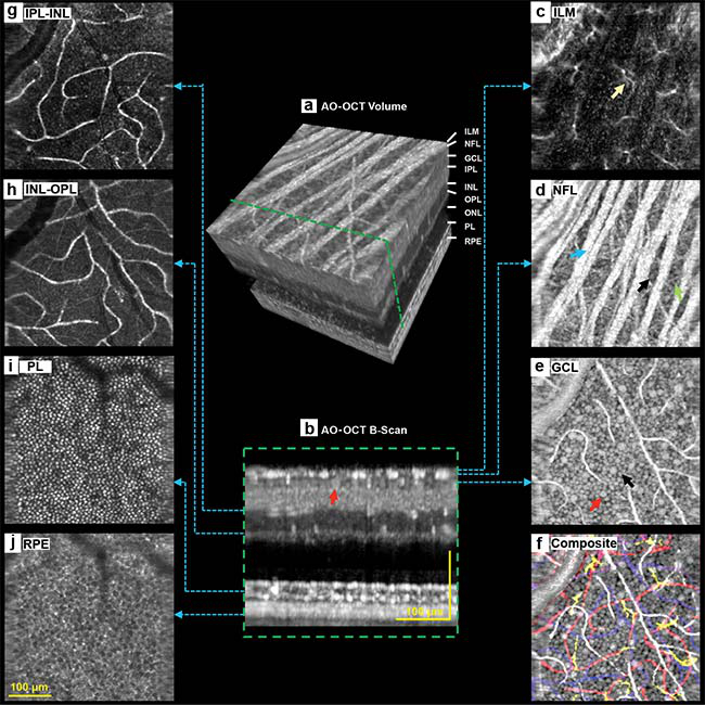
Figure 4. Detailed 3D imaging of retinal cellular structures using a multimodal AO-OCT system utilizing a Wasatch Photonics Cobra-S 800-nm spectrometer. AO-OCT volume of the retina (a), a single AO-OCT B-scan (b), starlike microglial cells speckling the inner limiting membrane (c), nerve fiber layer showing nerve fiber bundles (d), ganglion cell layer showing a mosaic of somas (e), a composite image overlaying multiple colorized layer images (f), capillaries spanning the IPL-INL and INL-OPL boundaries (g, h), photoreceptor layer (i), retinal pigment epithelium (j). Courtesy of Zhuolin Liu and Daniel X. Hammer.
High-speed AO-OCT imaging proved particularly well suited to resolving more weakly scattering RGCs in the inner retina (retinal ganglion cells) and RPEs in the outer retina (the pigmented cell layer that nourishes retinal photoreceptor cells), even resolving the outer segment tip of the rod and the epithelium layers of the retinal pigment, which are often not separated in conventional OCT imaging. As a whole, this multimodal approach offers a unified system for the study of retinal structure and physiology that could aid in the development of new treatments for highly prevalent eye diseases such as glaucoma and AMD.
Next steps for development
The success of AO-OCT depends on more than just advancements in imaging speed. Precise wavefront control requires a deformable mirror, spatial light modulator, or MEMS-based device. The deformable mirrors that are popular in ophthalmic imaging act to control the incident wavefront by reshaping a reflecting membrane using a discrete set of magnetic actuators. Nanometer-level control and correction of higher-order aberrations requires many actuators, with stringent requirements on precision and stability.
As developments in deformable mirror technology promise to reduce the cost, size, and complexity of these devices, AO-OCT will improve imaging for a large portion of the clinical population and become more widely accepted. In fact, one applications-minded approach involves next-generation deformable mirrors that correct only critical lower-order aberrations instead of the much larger range of aberrations currently targeted. This has the potential to yield the same image quality as current AO-OCT technology at much lower cost and complexity, particularly when combined with high-speed SD-OCT technology.
Another development heralds sensorless AO, which forgoes the wavefront sensor in favor of utilizing image quality to adjust the deformable mirror. Removing the requirement for a wavefront sensor reduces both the size and the cost of the instrument, although the need for computationally complex algorithms can limit the imaging bandwidth.
Yet another interesting technique promising cellular-level resolution is computational AO-OCT, which uses the phase information carried by OCT data to correct for optical aberrations at different depths7. While their hardware is much simpler, computational techniques yield limited signal-to-noise ratio and require extremely fast imaging to avoid corruption of phase information by sample motion.
The future of AO-OCT
With its ability to visualize cellular structure in 3D at near-video rates, AO-OCT promises to be invaluable for many scientific, biological, and clinical applications. It is one of the very few techniques that allow us to visualize the cellular structure and the function of complex organs completely unperturbed, and in one of the clinically most relevant areas of the body. The increased resolution provided by AO-OCT has been invaluable in understanding the origins of layers seen close to the outer retina. It is shedding light on the progression of diseases such as geographic atrophy (GA) to suggest drug targets for as-yet untreatable conditions.
AO in combination with OCT angiography allows visualization and quantification of changes in microvascular structures that are critical to understanding diabetic retinopathy. AO-OCT has also shown early promise for better understanding and early diagnosis of glaucoma by imaging nerve fiber bundles in the retina and the lamina cribrosa in the optic nerve; the recent demonstration of AO-OCT to resolve the ganglion cell mosaic may soon change our understanding of glaucoma8.
But as promising as this technique has been in resolving retinal cells in vivo, the real value of AO-OCT can only be demonstrated through large-scale clinical studies specific to different disease domains via widespread adoption of AO-OCT instrumentation by the clinical community. Fortunately, the development of cost-effective commercial SD-OCT imaging products with high speed and sensitivity, bolstered by innovation in AO components and methods, are making this technique more accessible than ever.
These advancements — along with persistent efforts from vision scientists, ophthalmologists, and entrepreneurs — are bringing us closer to reaching a self-sustaining cycle of technological innovations and applications served by AO-OCT. If the eye is the window to the soul, then AO-OCT has the potential to throw open its sash.
Meet the authors
Nishant Mohan is vice president of the OCT division at Wasatch Photonics. He has actively participated in the strategy, marketing, research, and development of OCT for more than a decade, beginning at Bausch & Lomb Inc. in Rochester, N.Y., and as a research fellow at Harvard Medical School; email: nmohan@wasatchphotonics.com.
Cicely Rathmell is vice president of marketing at Wasatch Photonics. She has worked in the industry for 20 years, including in telecommunications, biotech, optical components, and spectroscopy. She holds an M.Sc. in physics from McMaster University; email: marketing@wasatchphotonics.com.
References
1. J. Liang et al. (1997). Supernormal vision and high-resolution retinal imaging through adaptive optics. J Opt Soc Am A, Vol. 14, Issue 11, pp. 2884-2892.
2. D.T. Miller et al. (2003). Coherence gating and AO in the eye. P Soc Photo-Opt Ins, Vol. 4956, https://doi.org/10.1117/12.477633.
3. B. Hermann et al. (2004). Adaptive optics ultrahigh-resolution optical coherence tomography. Opt Lett, Vol. 29, Issue 18, pp. 2142-2144.
4. R.J. Zawadzki et al. (2005). Adaptive-optics optical coherence tomography for high-resolution and high-speed 3D retinal in vivo imaging. Opt Express, Vol. 13, Issue 21, pp. 8532-8546.
5. O.P. Kocaoglu et al. (2014). AO optical coherence tomography at 1 MHz. Biomed Opt Express, Vol. 5, Issue 12, pp. 4186-4200.
6. Z. Liu et al. (2018). Trans-retinal cellular imaging with multimodal adaptive optics. Biomed Opt Express, Vol. 9, Issue 9, pp. 4246-4262.
7. N.D. Shemonski et al. (2015). Computational high-resolution optical imaging of the living human retina. Nat Photonics, Vol. 9, Issue 7, p. 440.
8. Z. Liu et al. (2017). Imaging and quantifying ganglion cells and other transparent neurons in the living human retina. Proc Natl Acad Sci, Vol. 114, Issue 48.
Best Scientific1993年成立于英国,在显微镜和视觉系统领域提供各种产品用于生命和材料科学。我们可以根据客户的要求定制参数,预算,应用以及时间框架等给他们推荐合适的产品。我们以合适的价格提供合适的产品。我们公司是一个全面的视觉系统集成商,如果有可能,最好将使用现有设备帮助你建立一个合适的系统。然而,我们也可以提供完整的视觉系统,有照明、照相机和光学系统来达到您的要求。
Nd:YAG激光分光镜 分光镜可将任意偏振态的激光光束平均分成互成90度的两束光。平均光强为:R=(Rs+Rp)/2 and T=(Ts+Tp)/2
Nd:YAG 激光分光镜包括:
– 材料BK7; 波长1064 nm, 尺寸ø12.7×3 mm or ø25.4×6 mm
– 材料 UVFS; 波长1064 nm, 尺寸ø12.7×3 mm or ø25.4×6 mm
– 材料BK7; 波长532 nm, 尺寸ø12.7×3 mm or ø25.4×6 mm
– 材料UVFS; 波长532 nm, 尺寸ø12.7×3 mm or ø25.4×6 mm
– 材料UVFS; 波长355 nm, 尺寸ø12.7×3 mm or ø25.4×6 mm
– 材料UVFS; 波长266 nm, 尺寸ø12.7×3 mm or ø25.4×6 mm